Telescope
Background
A telescope is a device used to form images of distant objects. The most familiar kind of telescope is an optical telescope, which uses a series of lenses or a curved mirror to focus visible light. An optical telescope which uses lenses is known as a refracting telescope or a refractor; one which uses a mirror is known as a reflecting telescope or a reflector. Besides optical telescopes, astronomers also use telescopes that focus radio waves, X-rays, and other forms of electromagnetic radiation. Telescopes vary in size and sophistication from homemade spyglasses built from cardboard tubes to arrays of house-sized radio telescopes stretching over many miles.
The earliest known telescope was a refractor built by the Dutch eyeglass maker Hans Lippershey in 1608 after he accidentally viewed objects through two different eyeglass lenses held a distance apart. He called his invention a kijker, "looker" in Dutch, and intended it for military use. In 1609, the Italian scientist Galileo Galilei built his own telescopes and was the first person to make astronomical observations using them. These early telescopes consisted of two glass lenses set within a hollow lead tube and were rather small; Galileo's largest instrument was about 47 inches (120 cm) long and 2 inches (5 cm) in diameter. Astronomers such as Johannes Kepler in Germany and Christian Huygens in Holland built larger, more powerful telescopes throughout the 1600s. Soon these telescopes got too large to be easily controlled by hand and required permanent mounts. Some were more than 197 feet (60 m) long.
The ability to construct enormous telescopes outpaced the ability of glassmakers to manufacture appropriate lenses for them. In particular, the problems caused by chromatic aberration (the tendency for a lens to focus each color of light at a different point, leading to a blurred image) became acute for very large telescopes. Scientists of the time knew of no way to avoid this problem with lenses, so they designed telescopes using curved mirrors instead.
In 1663, the Scottish mathematician James Gregory designed the first reflecting telescope. Alternate designs for reflectors were invented by the English scientist Isaac Newton in 1668 and the French scientist N. Cassegrain in 1672. All three designs are still in use today. In the 1600s, there was no good way to coat glass with a thin reflective film, as is done today to make mirrors, so these early reflectors used mirrors made out of polished metal. Newton used a mixture of copper, tin, and arsenic to produce a mirror which could only reflect 16% of the light it received; today's mirrors reflect nearly 100% of the light that hits them.
It had been known as early as 1730 that chromatic aberration could be minimized by replacing the main lens of the telescope with two properly shaped lenses made from two different kinds of glass, but it was not until the early 1800s that the science of glassmaking was advanced enough to make this technique practical. By the end of the 19th century, refracting telescopes with lenses up to a meter in diameter were constructed, and these are still the largest refracting telescopes in operation.
Reflectors once again dominated refractors in the 20th century, when techniques for constructing very large, very accurate mirrors were developed. The world's largest optical telescopes are all reflectors, with mirrors up to 19 feet (6 m) in diameter.
Raw Materials
A telescope consists of an optical system (the lenses and/or mirrors) and hardware components to hold the optical system in place and allow it to be maneuvered and focused. Lenses must be made from optical glass, a special kind of glass which is much purer and more uniform than ordinary glass. The most important raw material used to make optical glass is silicon dioxide, which must not contain more than one-tenth of one percent (0.1%) of impurities.
Optical glasses are generally divided into crown glasses and flint glasses. Crown glasses contain varying amounts of boron oxide, sodium oxide, potassium oxide, barium oxide, and zinc oxide. Flint glasses contain lead oxide. The antireflective coating on telescope lenses is usually composed of magnesium fluoride.
A telescope mirror can be made from glass that is somewhat less pure than that used to make a lens, since light does not pass through it. Often a strong, temperature-resistant glass such as Pyrex is used. Pyrex is a brand name for glass composed of silicon dioxide, boron oxide, and aluminum oxide. The reflective coating for telescope mirrors is usually made from aluminum, and the protective coating on top of the reflective coating is usually composed of silicon dioxide.
Hardware components that are directly involved with the optical system are usually manufactured from steel or steel and zinc alloys. Less critical parts can be made from light, inexpensive materials such as aluminum or acrylonitrile-butadiene-styrene plastic, commonly called ABS.
The Manufacturing
Process
Making the hardware components
- 1 Metal hardware components are manufactured using standard metalworking machines such as lathes and drill presses.
- 2 Components made from ABS plastics (usually the external body of the telescope) are produced using a technique known as injection molding. In this process the plastic is melted and forced under pressure into a mold in the shape of the final product. The plastic is allowed to cool back into a solid, and the mold is opened to allow the component to be removed.
Making optical glass
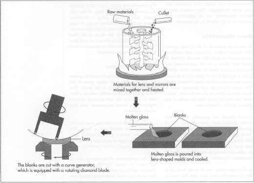
- 3 The glass manufacturer mixes the proper raw materials with waste glass of the same type as the glass to be made. This waste glass, known as cullet, acts as a flux; that is, it causes the raw materials to react together at a lower temperature than they would without it.
- 4 This mixture is heated in a glass furnace until it has melted into a liquid. The temperature needed to form molten glass varies with the type of glass being made, but it is typically about 2550°F (1400°C).
- 5 The temperature of the molten glass is raised to about 2820°F (1550°C) to force air bubbles to come to the surface. It is then allowed to cool while being stirred constantly until it has reached about 1830°F (1000°C), at which point it is an extremely thick fluid. This viscous, molten glass is poured into molds with roughly the same shape as the lenses required.
- 6 After the glass has cooled to about 570°F (300°C), it must be reheated to about 1020°F (550°C) to remove internal stresses that form during the initial cooling period and which weaken the glass. It is then allowed to cool slowly to room temperature. This process is known as annealing. The final lens-shaped chunks of glass are known as blanks.
Making the lenses
The blanks are processed by the telescope manufacturer in three steps: cutting, grinding, and polishing. A mirror is formed in exactly the same way as a lens until the reflective coating is applied.
-
7 First a high-speed, rotating cylindrical cutter with a round diamond
blade,
known as a curve generator, shaves the surface of the lens until a close approximation of the desired curve is achieved. The cut lens is inspected with a spherometer to check the curvature and is recut if necessary. The time required for cutting varies greatly with the type of glass being cut and the kind of lens being shaped. A lens may require several cuttings, each of which may take anywhere from a few minutes to more than half an hour.
- 8 Several cut blanks are placed on a curved block in such a way that their surfaces line up as if they were all part of one large spherical curve. This is necessary so that the grinding machine can grind them all in the same way. A cast iron grinding surface known as a tool is pressed onto them. During grinding, the block of lenses rotates while the tool is free to move at random on top of it. Between the tool and the block flows a slurry containing water, an abrasive to do the grinding (usually silicon carbide), a coolant to prevent the lenses from being damaged by overheating, and a surfactant to keep the abrasive from settling out. The speed at which the block rotates, the force placed on the lenses, the exact contents of the slurry, and other variables are controlled by experienced opticians to produce the exact type of lens desired. Each lens is once again inspected with a spherometer and reground if necessary. The total grinding process may take anywhere from one hour to eight hours. The ground lenses are cleaned and moved to the polishing room.
-
9 The polishing machine is similar to the grinding machine, but the tool
is made from pitch—a thick, soft, resinous substance derived from
coal tar or wood tar. A pitch tool is made by placing tape around the
circumference of a curved dish, pouring in hot, liquid pitch with other
ingredients such as beeswax and jeweler's rouge, and letting it
cool back into a solid. A pitch tool can polish about 50 lenses before it must be reshaped. Polishing proceeds in the same manner as grinding, but instead of an abrasive the slurry contains a polishing substance, usually cerium dioxide, in the form of a very fine pink powder. The polished lenses are optically inspected and repolished if necessary. The polishing procedure may take anywhere from half an hour to four or five hours. The lenses are cleaned and are ready for coating.

Applying coatings
- 10 To make a lens into a mirror, a very thin, very smooth coating of aluminum is applied. Aluminum is heated in a vacuum to form a vapor. A negative electro-static charge is applied to the surface of the lens so that the positively charged aluminum ions are attracted to it. Similar procedures are followed to apply a coating of silicon dioxide to protect the fragile surface of a mirror or to apply an antireflective coating of magnesium fluoride to the surface of a lens. The finished lens or mirror is inspected, labeled with a date of manufacture and a serial number, and stored until needed.
Assembling and shipping the telescope
- 11 The hardware components, lenses, and mirrors required to make a particular model of telescope are assembled by hand in an assembly line process. The completed telescope is packed with close-fitting expanded polystyrene foam to protect it from damage during shipping. The telescope is packed in a cardboard box and shipped to the retailer or consumer.
Quality Control
The most critical aspect of quality control for an optical telescope is the accuracy of the lenses and mirrors. During the cutting and grinding stages, the physical dimensions of the lens are measured very carefully. The thickness and the diameter of the lens are measured with a vernier caliper, an instrument which looks something like a monkey wrench. The outer, fixed jaw of the caliper is placed against one side of the lens and the inner, sliding jaw is gently moved until it meets the other side of the lens. In a classic vernier caliper, the dimensions of the lens are read very accurately using a scale which moves along with the inner jaw and which is compared with a stationary scale attached to the outer jaw. This type of caliper works much like a slide rule. There also exist electronic versions of this instrument, in which the measured dimension automatically appears on a digital display.
The curvature of a lens is measured with a spherometer, a device which resembles a pocket watch with three small pins protruding from its base. The outer two pins are fixed in place while the inner pin is free to move in and out. The spherometer is gently placed on the surface of the lens. Depending on the type of curve, the middle pin will either be higher than the other two pins or lower than the other two pins. The movement of the inner pin moves a needle on a calibrated dial on the face of the spherometer. This value is compared with the standard value that should be obtained for the desired curvature.
Tolerances vary with the type of lens being manufactured, but a typical acceptable variation might be plus or minus 0.0008 inches (20 micrometers). For a flat lens, generally one destined to become a flat mirror, the tolerance is much smaller, usually about plus or minus 0.00004 inches (1.0 micrometer).
During the polishing stage, these instruments are not accurate enough to ensure that the lens will work properly. Optical tests, which measure the way light is affected by the lens, must be used. One common test is known as an autocollimation test. The lens is placed in a dark room and is illuminated with a low intensity pinpoint light source. A diffraction grating (a surface containing thousands of microscopic parallel grooves per inch) is placed at the point where the lens should focus light. The grating causes an interference pattern of dark and light lines to form in front of and behind the focal point. The true focal point can thus be found precisely and compared with the theoretical focal point for the type of lens desired.
In order to test a flat lens, a lens that is known to be flat is placed face down on the lens that is to be tested, which rests on a piece of black felt. The microscopic gaps between the two lenses cause an interference pattern to appear when gentle pressure is applied. The light and dark lines are known as Newton's rings. If the lens being tested is flat, the lines should be straight and regular. If the lens is not flat, the lines will be curved.
The Future
The techniques used to produce excellent lenses and mirrors have been well under-stood for many years, and major innovations in this area are unlikely. One area of active research is in coating technology. New coating substances may be developed to provide better protection for mirrors and better prevention of loss of light through reflection for lenses.
A more dramatic area of progress is in the electronic accessories that accompany telescopes. Amateur astronomers will soon be able to obtain telescopes with built-in computer guidance systems that will enable them to automatically point the telescope at a selected celestial object and to track it night by night. They will also be able to attach video cameras to their telescopes and film such astronomical phenomena as lunar eclipses and the movements of planets and moons.
Where To Learn More
Books
Asimov, Isaac. Eyes on the Universe: A History of the Telescope. Houghton Mifflin, 1975.
Bell, Louis. The Telescope. Dover, 1981.
Manly, Peter L. Unusual Telescopes. Cambridge University Press, 1991.
Periodicals
Mullins, Mark. "A Truly Economical Telescope." Sky and Telescope, December 1993, pp. 91-92.
Nash, J. Madeleine. "Shoot for the Stars." Time, April 27, 1992, pp. 56-57.
Nelson, Ray. "Reinventing the Telescope." Popular Science, January 1995, pp. 57-59, 85.
— Rose Secrest
Comment about this article, ask questions, or add new information about this topic: