Draw Bridge
Background
A bridge over a navigable waterway must allow boats and ships to cross its path, usually by being tall enough to allow them to sail underneath it. Sometimes it is impractical to build a bridge high enough; for example, it may rise too steeply or block the view of an important landmark. In such cases, the bridge can be designed so it can be easily moved out of the way for vessels that are too large to sail under it.
The type of movable bridge that most people think of as a draw bridge is similar to those that spanned medieval castle moats. Technically called "bascule bridges" from the French word for seesaw, they may open at one end and lift to one side (single leaf) or open in the middle and lift to both sides (double leaf). Another common type of movable bridge is the vertical lift span, in which the movable section is supported at both ends and is raised vertically like an elevator. Retractable bridges are made so the movable span slides back underneath an adjacent section of the bridge. Swing bridges are supported on vertical pivots, and the movable span rotates horizontally to open the bridge.
Movable bridges are relatively rare because they are more expensive to operate and maintain than stationary bridges. They also impede traffic—on the water when they are closed and on the roadway or rail line when they are open. Of the 770 bridges for which the New York City Transportation Department is responsible, 25 are movable bridges, including at least one of each of the four types defined above.
History
A few ancient drawbridges were built, including one 4,000 years ago in Egypt and one 2,600 years ago in the Chaldean kingdom of the Middle East. But they were not commonly used until the European Middle Ages. By the end of the fifteenth century, Leonardo da Vinci was not only designing and building bascule bridges but also drawing plans and constructing scale models for a swing bridge and a retractable bridge.
The modern era of movable bridge construction began in the mid-nineteenth century following the development of processes for mass producing steel. Steel beams are light and strong, steel bearings are durable, and steel engines and motors are powerful.
Many of the movable bridges currently in use in the United States were built in the early twentieth century. As they are being refurbished or replaced, two types of improvements can be made. First, more sophisticated design techniques and stronger, lighter materials allow new bridges to be built higher above the water. This means larger vessels can sail under them; consequently, it is not necessary to open them as frequently. Some modern replacements must be opened only one-fourth to one-third as often their predecessors. Second, some new bridges are operated hydraulically rather than being driven with gear mechanisms.
Raw Materials
Draw bridges are made primarily from concrete and steel. Seventy-five hundred short tons (6,804 metric tons) of structural steel and 150,000 short tons (13,6080 metric tons) of concrete were used in the Casco Bay Bridge
Design
Each draw bridge is a unique structure designed for its particular location and traffic needs. There are at least half a dozen different design concepts, but the most common is the bascule type. In double-leaf or four-leaf (a double-leaf bridge with separate leaves for each direction of vehicular traffic) bascule bridges, each leaf can be raised and lowered independently.
The energy required to raise and lower the bascule leaves is greatly reduced by counterbalancing each leaf with a compact weight on the opposite side of the pivot axle (trunnion). In various bascule designs, this counterweight might be located above the roadway and allowed to pivot below the roadway as the bridge is raised, or it might be located below the roadway and allowed to descend into a basement level (often well below the waterline) as the bridge opens. The counterweight is a massive concrete box containing chambers into which heavy, metal rods can be inserted to change the weight and its distribution. It might be located adjacent to the trunnion or, for greater leverage, be set back a few yards (meters). As an example, each pair of 500-ton (450-metric-ton) leaves on the Casco Bay Bridge is balanced with an 800-ton (720-metric-ton) counterweight.
Besides the leaves and the counterweights, the other primary elements of a bascule bridge are the trunnion and the lift mechanism. A single steel trunnion up to 10 ft (3 m) in diameter and 65 ft (20 m) or more in length may be used for one leaf of the movable span; or a separate, short trunnion may be used for each side of each leaf. The lift mechanism is usually a rack-and-pinion gear arrangement driven by electric motors.
The Manufacturing Process
Although each installation is different, the following is a generic description of the construction of a bascule bridge.
Piers
-
1 If the bascule support piers will be located in the water, a cofferdam
is built around the site for each pier. Steel panels are lowered into
the water and driven into the riverbed to form a box. A clamshell digger
removes soil inside the cofferdam. Piles are inserted deep into the riverbed to support the great weight of the pier and the bascule leaves. Steel piles may be driven, or reinforced concrete piles may be poured, into drilled holes. The bottom of the cofferdam is sealed with a layer of concrete. The water is pumped out of the cofferdam to provide a dry area for constructing the pier.
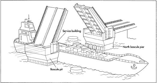
 A. Bascule pit. B. Fender system. C. Bridge pier.
 - 2 Forms are built to shape the concrete piers. Steel bars (rebar) are tied together to make a carefully designed reinforcing cage for the interior of the pier. The rebar cage is lowered into position inside the forms. The forms are filled with concrete. When the concrete has hardened, the forms are removed. Around the waterline, a protective layer of an erosion-resistant material, such as granite, may be attached to the pier. The cofferdam is removed.
- 3 A fender may be built around the pier to protect it from being hit by errant ships. For example, on the Casco Bridge, large concrete cylinders were erected upstream and downstream from each pier to support the ends of a steel fender. The fender was faced with slippery plastic to deflect minor impacts. Under heavier impacts, the fender can deflect against rubber bumpers and, if necessary, against crushable hollow concrete boxes that would keep the impact from damaging the pier itself.
Bascule leaves
- 4 One or more trunnions are mounted on supports within the pier.
- 5 A counterweight is constructed and placed inside the pier.
- 6 Gear drives and/or hydraulic lift mechanisms are installed in the pier.
- 7 Two side girders are constructed for the heel section of each leaf of the bridge. A trunnion bearing is mounted in an opening in each girder. The girder may be equipped with gears that will mesh with the lift mechanism, or it may be fitted with paddles that hydraulic rams can push against.
- 8 The two side girders are lifted into the pier and eased over the ends of the trunnion. The heel section is completed with a crossbeam connecting the two side girders. The counterweight is attached to the heel section.
- 9 Additional longitudinal girders may be hoisted into position between the side girders and attached to the heel section. Steel braces are attached between the side girders and any other longitudinal girders. As pieces are added to the leaf, an appropriate amount of weight must also be added to the counterweight to maintain stability. This is particularly important if the bridge is being built in the closed position and must be opened during construction to allow marine traffic to pass.
- 10 The leaf is completed by attaching a tip section that connects the side girders (and any longitudinal girders) at the end opposite the heel. Devices called span locks are mounted on the leaf tips to connect opposite leaves when the bridge is down, so that vehicles driving on the bridge will not make the leaves bounce. Additional locks can secure the leaves in their open position so wind does not force them back down.
Finishing
- 11 Panels of steel-grate decking are installed atop the leaf. Sometimes a thin concrete surface is added.
- 12 Final balancing is accomplished by placing heavy iron, steel, or lead rods in the correct counterweight compartments. When properly balanced, the leaf is slightly heavier than the counterweight so gravity gently lowers (closes) the bridge.
Ongoing Adjustments
Throughout the lifetime of the bridge, counterweight adjustments must be made. Shortterm adjustments compensate for ice or snow accumulations, for example. Longterm adjustments balance leaf weight changes due to activities such as repaving or painting. When the 250-foot (75-m) long High Street Bridge in Alameda County, California, was refurbished in 1996, 25,000 pounds (11,000 kg) of paint and primer were removed from its two bascule leaves. The counterweights had to be adjusted before and after repainting the span.
A dramatic example of the need to maintain proper counterbalance was shown by an accident on Chicago's Michigan Avenue Bridge on September 20, 1992. The two-level, double-leaf bascule bridge was under-going repairs, and the concrete paving had been stripped off both the upper and lower decks. A large crane was parked behind the trunnion of one leaf, just above a counter-weight that had not been lightened to compensate for the paving removal. Safety locks may also have been improperly engaged or defective. The opposite side of the bridge was opened to allow a boat to pass. When it closed and mated with the side that had remained down, the static half was jarred enough to release its unbalanced energy. The leaf "sprang up without warning, like a gargantuan catapult, hurling equipment and debris hundreds of feet across Wacker Drive into buses, automobiles, and pedestrian traffic," according to an analysis in the Journal of the American Society of Mechanical Engineers. The article continued, "The rapid rotation of the bridge ripped it from its trunnion bearings and the entire span slammed to the bottom of the counterweight pit." Six people were injured as they scrambled out of a bus struck by flying debris, and the rear window of an occupied car was smashed by the wrecking ball attached to the crane as it fell from the bridge.
The Future
There are two categories of movable bridge innovations. Refinements of traditional designs include minimizing the construction of large, submerged pits to receive counter-weights when the bridge is open. For example, the 17th Street Causeway Bridge in Fort Lauderdale, Florida, begun in 1998, allows compact counterweights to swing within V-shaped support piers rather than down into basements below bulky piers. The South Eighth Street Bridge in Sheboygan, Wisconsin, completed in 1995, operates without any counterweight despite its comparatively heavy, reinforced concrete deck. Rather than being gear-driven, the 82-ft (25-ni) long single-leaf bascule is moved by a powerful hydraulic system.
Other movable bridge innovations introduce entirely new concepts. For instance, the Baltic Millennium Bridge in Gateshead, England (to be opened to the public in 2001), consists of two parabolic arches connected by a series of parallel cables. When the bridge is closed, one arch is horizontal and the other is vertical. The bridge opens by rotating vertically as a complete unit, raising the horizontal arch and lowering the vertical one until both rest approximately 45° and 164 ft (50 m) above the water surface. The steel and aluminum structure is designed to carry pedestrian and bicycle traffic across the 410-ft (125-m) wide River Tyne.
Where to Learn More
Periodicals
"Arched Cable-Stayed Crossing Tilts Side-ways to Open." Civil Engineering (May 1999): 17+.
Cassity, Patrick A., et al. "Rebound of the Bascule Bridge." Civil Engineering (August 1996): 48+.
Studney, Michael J. &lquo;When a Bridge Becomes a Catapult." Mechanical Engineering (December 1992): 51+.
Other
17th Street Causeway. http://www.dot.state.fl.us/structures/botm/17thstreet/17thstreet.htm . (May 2, 2000).
Watson, Sara Ruth, and John R. Wolfs. Bridges of Metropolitan Cleveland. (1998). http://web.ulib.csuohio.edu/SpecColl/bmc/index.html (May 3, 2000).
— Loretta Hall
Peter Summers