Gyroscope
Background
The gyroscope is a familiar toy that is deceptively simple in appearance and introduces children to several mechanical principles, although they may not realize it. Something like a complex top made of precisely machined metal, the gyroscope is a spinning wheel that may be set within two or more circular frames, each oriented along a different line or axis. The framework can be tilted at any angle, and the wheel—as long as it is spinning—will maintain its position, or attitude.
But the gyroscope is not just a toy. It is a part of many scientific and transportation-related instruments. These include compasses, the mechanisms that steer torpedoes toward their targets, the equipment that keeps large ships such as aircraft carriers from rolling on the waves, automatic pilots on airplanes and ships, and the systems that guide missiles and spacecraft relative to Earth (that is, inertial guidance systems).
The gyroscope consists of a central wheel or rotor that is mounted in a framework of rings. The rings are properly called gimbals, or gimbal rings. Gimbals are devices that support a wheel or other structure but allow it to move freely. The rings themselves are supported on a spindle or axis at one end that, in turn, can be mounted on a base or inside an instrument. The property of the rotor axle to point toward its original orientation in space is called gyroscopic inertia; inertia is simply the property of a moving object to keep moving until it is stopped. Friction against the air eventually slows the gyroscope's wheel, so its momentum erodes away. The axle then begins to wobble. To maintain its inertia, a gyroscope must spin at a high speed, and its mass must be concentrated toward the rim of the wheel.
History
The gyroscope is a popular children's toy, so it is no surprise that its ancestor is the spinning top, one of the world's oldest toys. A single-frame gyroscope is sometimes called a gyrotop; conversely, a top is a frameless gyroscope. In the sixteenth through eighteenth centuries, scientists including Galileo (1564-1642), Christiaan Huygens (1629-1695), and Sir Isaac Newton (1642-1727) used toy tops to understand rotation and the laws of physics that explain it. In France during the 1800s, the scientist Jean-Bernard-Léon Foucault (1819-1868) studied experimental physics and proved Earth's rotation and explained its effect on the behavior of objects traveling on Earth's surface. In the 1850s, Foucault studied the motions of a rotor mounted in a gimbal frame and proved that the spinning wheel holds its original position, or orientation, in space despite Earth's rotation. Foucault named the rotor and gimbals the gyroscope from the Greek words gyros and skopien meaning "rotation" and "to view."
It was not until the early 1900s that inventors found a use for the gyroscope. Hermann Anschiutz-Kaempfe, a German engineer and inventor, recognized that the stable orientation of the gyroscope could be used in a gyrocompass. He developed the gyrocompass for use in a submersible for undersea exploration where normal navigation and orientation systems are impractical. In 1906, Otto Schlick tested a gyroscope equipped with a rapidly spinning rotor in the German torpedo boat See-bar. The sea caused the torpedo boat to roll 15° to each side, or 30° total; when his gyroscope was operated at full speed, the boat rolled less than 1° total.
In the United States, Elmer Ambrose Sperry (1860-1930)—an inventor noted for his achievements in developing electrical loco-motives and machinery transmissions—introduced a gyrocompass that was installed on the U.S. battleship Delaware in 1911. In 1909, he had developed the first automatic pilot, which uses the gyroscope's sense of direction to maintain the course of an airplane. The Anschiütz Company installed the first automatic pilot—based on a three-frame gyroscope—in a Danish passenger ship in 1916. In that year, the artificial horizon for aircraft was designed as well. The artificial horizon tells the pilot how the airplane is rolling (moving side to side) or pitching (moving front to rear) when the visible horizon vanishes in the clouds or other conditions.
Roll-reduction was needed for ships, too. The Sperry Company had introduced a gyrostabilizer that used a two-frame gyroscope in 1915. The roll of a ship on the ocean makes passengers seasick, causes cargo to shift and suffer damage, and induces stresses in the ship's hull. Sperry's gyrostabilizer was heavy, expensive, and occupied a lot of space on a ship. It was made obsolete in 1925 when the Japanese devised an underwater fin for stabilizing ships.
During the intense development of missile systems and flying bombs before and during World War II, two-frame gyroscopes were paired with three-frame instruments to correct roll and pitch motions and to provide automatic steering, respectively. The Germans used this combination on the V-1 flying bomb, the V-2 rocket, and a pilotless airplane. The V-2 is considered an early ballistic missile. Orbiting spacecraft use a small, gyroscope-stabilized platform for their navigation systems. This characteristic of gyroscopes to remain stable and define direction to a very high degree of accuracy has been applied to gunsights, bombsights, and the shipboard platforms that support guns and radar. Many of these mechanisms were greatly improved during World War II, and the inertial navigation systems that use gyroscopes for spacecraft were invented and perfected in the 1950s as space exploration became increasingly important.
Raw Materials
The materials used to manufacture a gyroscope can range from relatively simple to highly complex depending on the design and purpose of the gyroscope. Some are made more precisely than the finest watch. They may spin on tiny ball bearings, polished flecks of precious gemstones, or thin films of air or gas. Some operate entirely in a vacuum suspended by an electrical current so they touch nothing and no friction develops.
A gyroscope with an electrically powered motor and metal gimbals has four basic sets of components. These are the motor, the electrical components, electronic circuit cards for programmed operation, and the axle and gimbal rings. Most manufacturers purchase motors and electrical and electronic components from subcontractors. These may be stock items, or they may be manufactured to a set of specifications provided to the supplier by the gyroscope maker. Typically, gyroscope manufacturers machine their own gimbals and axles. Aluminum is a preferred metal because of its expansion and strength characteristics, but more sophisticated gyroscopes are made of titanium. Metal is purchased in bulk as bar stock and machined.
Design
Using the electrical and mechanical aspects of gyroscopic theory as their guides, engineers choose a wheel design for the gimbals and select metal stock appropriate for the design. The designs for many uses of gyroscopes are fairly standard; that is, redesign or design of a new line is a matter of adapting an existing design to a new use rather than creating a new product from the most basic beginning. Design does, however, involve observing the most fundamental engineering practices. Tolerances, clearances, and electronic applications are very precise. For example, design of the gimbal wheels and design of the machining for them has a very small tolerance for error; the cross section of a gimbal must be uniform throughout or the gyroscope will be out of balance.
The Manufacturing Process
-
The gimbals and gimbal frames are machined from aluminum bar stock using
tools developed as part of the design process. They are polished and cleaned and stored in bins until assembly. For assembly, the bins are moved to appropriate locations along the assembly line.
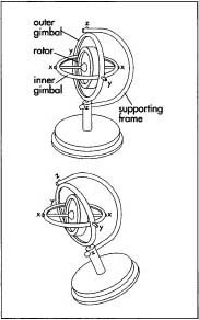 An example of a gyroscope.
 - Gyroscopes are manufactured in a straight-forward assembly line process that emphasizes the importance of "touch labor" over automation. Gyroscopes are assembled from the inside out. The motor is the heart of the gyroscope and is installed first. A "typical" gyroscope motor is synchronized to spin at 24,000 revolutions per minute (rpm). It must be perfectly synchronized, and the motor is typically bench-tested before assembly. Electrical connections are added to the motor.
- The gimbals and frames are assembled next, beginning with the inner gimbal and ending with the outer gimbal frame. Bearings are put into place. The "end play" of the bearings (the looseness of fit) typically has a very small tolerance of 0.0002-0.0008 in (0.006-0.024 mm).
- The outermost electrical connections are attached on the assembly line, and circuit cards are added. Finally, the gyroscope is calibrated at the end of the assembly process. The suspension of the bearings and calibration are hand checked; manufacturers have found that, for even calibration, human observation, testing, and correction are more trustworthy than automated methods.
The gyroscope is an elegant example of an application of simple principles of physics. Because it is simple, manufacturers closely guard any proprietary techniques. Because the gyroscope is a simple device with wideranging uses, some require more manufacturing processes. The manufacturing steps described above take about 10 hours and result in a free gyroscope for an application such as missile guidance. A more exotic gyroscope may require 40 hours of assembly time.
Quality Control
Quality control is essential throughout the design and assembly processes in manufacturing gyroscopes because the instruments are part of manned aircraft, unmanned missiles, and other transportation and weapons devices that could cause catastrophes if they fail. Engineers, scientists, and designers are highly educated and trained before they are hired and while on the job. Assembly-line workers must pass initial training to be hired, and they have regularly scheduled, ongoing training sessions. Many of the quality standards that must be met in gyroscope manufacture can be measured, so in-process inspection is performed throughout manufacture. Quality control at the highest level is performed by inspectors from outside the company and includes government inspectors. Customers also perform their own inspections and acceptance testing; if the manufacturer's product fails the customers' tests, the failed gyroscopes are returned.
Byproducts/Waste
Gyroscope manufacturers do not produce byproducts, but they tend to make full lines of gyroscopes for a wide variety of applications. They also do not produce much waste. Machining the gimbals and rings produces some aluminum chips, but these are collected and returned to the aluminum supplier for recycling.
Safety Concerns
Manufacturers observe the mandates of the Occupational Safety and Health Administration (OSHA) for light, ventilation, and ergonomics (comfortable seating and work benches that reduce the likelihood of repetitive stress injuries). Humidity must be maintained in the plant to prevent electrostatic discharge. Minor quantities of cleaning solvents are required, but citrus-based cleaners that are benign (harmless) are used.
The Future
Uses for gyroscopes are increasing with the number of devices that require guidance and control. Although the basics of the gyroscope are grounded in the laws of physics and can never change, the technology is evolving. Mechanical and electrical methods for providing the spinning mass that makes the gyroscope work are gradually being replaced by ring lasers and microtechnology. Coils of thin optical fibers hold the key to compact, lightweight gyroscopes that might have applications in navigation systems for automobiles. The gyroscope is such a simple but sophisticated instrument for keeping so many tools in transportation, exploration, and industry in balance that, seen or unseen, it certainly has a place in the future.
Where to Learn More
Books
Campbell, R. W. Tops and Gyroscopes. New York: Thomas Y. Crowell Company, 1959.
Langone, John. National Geographic's How Things Work: Everyday Technology Explained. Washington, DC: National Geographic Society, 1999.
Sparks, James C., Jr. Gyroscopes: What They Are and How They Work. New York: E. P. Dutton & Co., Inc., 1963.
Walton, Harry. The How and Why of Mechanical Movements. New York: Popular Science Publishing Company, E. P. Dutton & Co., Inc., 1968.
Periodicals
"A Gyroscope's Gravity-defying Feat." Science News 137, no. 1 (January 6, 1990): 15.
Scott, David. "Optical-fiber Gyro." Popular Science 230 (June 1987): 25.
Other
Gyroscopes as Propulsion Devices. http://www.gyro-scope.co.uk (July 2000).
Gyroscope Study Guide. http://clubknowledge.com/study/gyro.html (July 2000).
How a gyroscope works. http://www.accs.net/users/cefpearson/gyro.htm (July 2000).
— Gillian S. Holmes
what r the lattest tecnology of gyroscopic effect is use for four wheeler?.
tell all that things for the engineering study purpose thanks