Speedometer
Background
A speedometer is a device used to measure the traveling speed of a vehicle, usually for the purpose of maintaining a sensible pace. Its development and eventual status as a standard feature in automobiles led to the enforcement of legal speed limits, a notion that had been in practice since the inception of horseless carriages but had gone largely ignored by the general public. Today, no automobile is equipped without a speedometer intact; it is fixed to a vehicle's cockpit and usually shares a housing with an odometer, which is a mechanism used to record total distance traveled. Two basic types of automobile speedometer, mechanical and electronic, are currently produced.
History
The concept of recording travel data is almost as old as the concept of vehicles. Early Romans marked the wheels of their chariots and counted the revolutions, estimating distance traveled and average daily speed. In the eleventh century, Chinese inventors came up with a mechanism involving a gear train and a moving arm that would strike a drum after a certain distance. Nautical speed data was recorded in the 1500s by an invention called the chip log, a line knotted at regular intervals and weighted to drag in the water. The number of knots let out in a set amount of time would determine the speed of the craft, hence the nautical term "knots" still applied today.
The first patent for a rotating-shaft speed indicator was issued in 1916 to inventor Nikola Tesla. At that time, however, speedometers had already been in production for several years. The development of the first speedometer for cars is often credited to A. P. Warner, founder of the Warner Electric Company. At the turn of the century, he invented a mechanism called a cut-meter, used to measure the speed of industrial cutting tools. Realizing that the cut-meter could be adapted to the automobile, he modified the device and set about on a large promotional campaign to bring his speedometer to the general public. Several speed indicator concepts were introduced by competing sources at the time, but Warner's design enjoyed considerable success. By the end of World War I, the Warner Instrument Company manufactured nine out of every 10 speedometers used in automobiles.
The Oldsmobile Curved Dash Runabout, released in 1901, was the first automobile line equipped with a mechanical speedometer. Cadillac and Overland soon followed, and speedometers began to regularly appear as a factory-installed option in new automobiles. Speedometers in this era were difficult to read in daylight and, with no lamp in the housing, virtually illegible at night. The drive cable in early models was attached to either the front wheels or the back of the transmission, but the integration of the drive cable into the transmission housing wouldn't happen for another 20 years. After that improvement was made, the basic technical design of a speedometer would remain untouched until the advent of the electronic speedometer in the early 1980s.
Raw Materials
Materials used in the production of speedometers vary with the type of gauge and intended application. Older mechanical models were entirely comprised of steel and other metal alloys, but in later years about 40% of the parts for a mechanical speedometer were molded from various plastic polymers. Newer electronic models are almost entirely made of plastics, and design engineers continually upgrade the polymers used. For example, the case of a speedometer's main assembly is usually made of nylon, but some manufacturers now employ the more water-resistant polybutylene terephthalate (PBT) polyester. The worm drive and magnet shaft are also nylon, as is the speedometer's gear train and spindles. The glass display lens of the recent past is now made of transparent polycarbonate, a strong, flexible plastic that is resistant to heat, moisture, and impact.
Design
In a mechanical speedometer, a rotating cable is attached to a set of gears in the automobile's transmission. This cable is directly attached to a permanent magnet in the speedometer assembly, which spins at a rate proportional to the speed of the vehicle. As the magnet rotates, it manipulates an aluminum ring, pulling it in the same direction as the revolving magnetic field; the ring's movement, however, is counteracted by a spiral spring. Attached to the aluminum ring is the pointer, which indicates the speed of the vehicle by marking the balance between these two forces. As the vehicle slows, the magnetic force on the aluminum ring lessens, and the spring pulls the speedometer's pointer back to zero.
Electronic speedometers are almost universally present in late-model cars. In this type of gauge, a pulse generator (or tach generator) installed in the transmission measures the vehicle's speed. It communicates this via electric or magnetic pulse signals, which are either translated into an electronic read-out or used to manipulate a traditional magnetic gauge assembly.
The Manufacturing
Process
Steel components
- 1 To form molten steel, iron ore is melted with coke, a carbon-rich substance that results when coal is heated in a vacuum. Depending on the alloy, other metals such as aluminum, manganese, titanium, and zirconium may also be introduced. After the steel cools, it is formed into sheets between high-pressure rollers and distributed to the manufacturing plant. There, the individual parts may be cast into molds or pressed and shaped from bar stock by large rolling machines.
Plastic components
- 2 The various plastics that arrive in an instrument manufacturing station were first created from organic chemical compounds derived from petroleum. These polymers are distributed in pellet form for use in the injection-molding process. To make the small parts for a speedometer assembly, these pellets are loaded into the hopper of a molding machine and melted. A hydraulic screw forces the plastic through a nozzle and into a pre-cast mold, where the plastic is allowed to cool and solidify. The parts are then gathered and transported to assembly stations.
Assembly
- 3 The manner of assembly and degree of human interaction depends on the quality of speedometer. Some inexpensive speedometer systems are made to be "disposable," meaning that the instruments are not built for easy disassembly or repair. In this case, the hardware is fastened using a process called riveting, in which a headed pin is inserted and blunted on the other end, forming a permanent attachment. Higher-end speedometer systems consist of two major assemblies attached by screws; the advantage is that the inner hardware of the gauge is accessible for repair and recalibration.
-
4 The inner shaft and speedometer assembly are then fused into place
with rivets or screws. The permanent magnets used in mechanical
speedometers are compressed and molded before arrival at the plant, and
therefore only require mounting onto the worm drive. In the case of
electronic speedometers, fiberglass-and-copper circuitry is also
manufactured by vendors, and does require programming before it is
screwed into the larger system. These larger components are transported
to a separate assembly station, where they are mounted into the housing
with stud-terminal or blade-terminal plastic connectors. Beyond its
primary
duty as a protective case, the housing also serves as a platform for attaching exterior features such as the dial face, needle, and display window. Again, these processes require automation due to large output, but human effort is needed at every step to inspect and ensure product consistency.
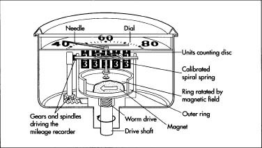 The inner mechanisms of a speedometer.
Calibration
- 5 Calibration is the process of determining the true value of spaces in any graduated instrument. It is an especially vital process in the manufacture of speedometers because driver safety is reliant on an accurate readout. In a mechanical gauge, magnetic forces produce the torque that deflects the indicator needle. When calibrating this type of gauge, an electromagnet is used to adjust the strength of the permanent magnet mounted in the speedometer until the needle matches the input from the rotating cable. When calibrating an electronic gauge, adjustments are made when calibration factors are written into the memory of the meter. The system can then refigure the balance between input from the transmission and output of the needle. New automated systems for calibrating both mechanical and electronic speedometers are now available, saving an immense number of the man-hours usually required for this process.
Quality Control
Probably the most direct method of quality control is the calibration process. Auto parts manufacturers work under the measurement standards developed by International Organization for Standardization (ISO), which ensures that universal guidelines between gauge manufacturers are used. In-house quality assurance teams develop specifications for each new product before it moves to the assembly line, and the same teams later report whether those guidelines are adhered to on the factory floor. Gradual levels of assembly also involve inspection by factory personnel to make sure that the automation is working smoothly.
Byproducts/Waste
No byproducts result from the manufacture of gauges. Waste materials include scrap metals and plastics, some of which can be reused in later production runs. Because the raw materials involved are prepared outside of the factory, no significant amount of hazardous industrial waste results from manufacture. Emissions from factory automation are government-regulated and surveyed by environmental protection groups.
The Future
Design firms are currently experimenting with improvements in speedometer readout, an effort to eliminate the moment of distraction needed for a driver to look down and gauge his or her speed. Digital readouts projected onto the windshield appear to be the next developmental step. Some proto-types for these speedometers actually make the readout appear as though it is floating over the engine hood. Because this type of display looks as though it is several feet beyond the steering wheel, drivers will be able to continually monitor speed without having to take their eyes off the road. The mirrors and projection devices used in this system could also be adjusted to suit the driver's position, much in the same way that a rear-view mirror does. In addition, speedometer projection systems will eventually be integrated with navigation tools, allowing directional information to appear with gauge readouts.
Where to Learn More
Other
Devaraj, Ganesh, et al. "Automating Speedometer Calibration." Evaluation Engineering Web Page. December 2001. < http://www.evaluationengineering.com/archive/articles/1100auto.htm >.
"How a Tachometer/Speedometer Works Using a Magnetic Sensor." Manual. Stewart-Warner Co., April 2001.
"How an Electrical Gauge is Put Together." Manual. Stewart-Warner Co., April 2001.
"How Odometers Work." Marshall Brain's How Stuff Works. December 2001. < http://www.howstuffworks.com >.
"Speeding Through Time." Transport Topics Electronic Newspaper. November 1998. December 2001. < http://www.ttnews.com/members/printEdition/0000395.html >.
"Speedometer." Complete Computer Software Web Page. December 2001. < http://www.iao.com/howthing/Default.htm >.
"The Floating Speedometer." Siemens.com Web Page. December 2001. < http://www.siemens.com/page/1,3771,257095-1-999_5_4-0,00.html >.
Kate Kretschmann
Comment about this article, ask questions, or add new information about this topic: