Jet Engine
Background
The jet engine is the power plant of today's jet aircraft, producing not only the thrust that propels the aircraft but also the power that fuels many of the aircraft's other systems.
Jet engines operate according to Newton's third law of motion, which states that every force acting on a body produces an equal and opposite force. The jet engine works by drawing in some of the air through which the aircraft is moving, compressing it, combining it with fuel and heating it, and finally ejecting the ensuing gas with such force that the plane is propelled forward. The power produced by such engines is expressed in terms of pounds of thrust, a term that refers to the number of pounds the engine can move.
The jet engine, like many technological innovations, took a long time to progress from concept to design to execution. The first attempts to transcend the traditional piston engine were actually modifications of that engine, both heavy and complex. The turbine design was introduced in 1921, and it and the other basic components of the modern jet engine were present in a design for which a Royal Air Force lieutenant named Frank Whittle received an English patent in 1930. Although testing on Whittle's engine began in 1937, it did not fly successfully until 1941. Across the English Channel in a Germany rushing to arm itself for World War II, similar but entirely separate work had begun with a 1935 jet engine patent issued to Hans von Ohain. Four years later, a team of German engineers led by Dr. Max Hahn achieved success, conducting the first entirely jet-powered flight in history. Upon achieving success with the Whittle engine in 1941, the British promptly shipped a prototype to their allies in the United States, where General Electric immediately began producing copies. The first American jet engine, produced by G.E., took flight in a plane constructed by Bell Aircraft late in 1942. Although use of jets was somewhat limited during World War II, by the end of the war all three countries had begun to utilize elite squadrons of jet-powered fighter planes.
Today's commercial engines, up to eleven feet in diameter and twelve feet long, can weigh more than 10,000 pounds and produce more than 100,000 pounds of thrust.
Design
A jet engine is contained within a cowling, an extermal casing that opens outward, somewhat like a rounded automobile hood, to permit inspection and repair of the interior components. Attached to each engine (a typical 747 uses four) is a pylon, a metal arm that joins the engine to the wing of the plane. Through pumps and feed tubes in the pylons, fuel is relayed from wing tanks to the engine, and the electrical and hydraulic power generated by the engine is then routed back to the aircraft through wires and pipes also contained in the pylons.
At the very front of the engine, a fan helps to increase the flow of air into the engine's first compartment, the compressor. As the fan drives air into it, the compressor—a metal cylinder that gradually widens from front to rear—subjects the incoming air to increasing pressure. To accelerate the progress of the air through the engine, the compressor is fitted with blades that rotate like simple household fans. In the incredibly brief time it takes air
Expanding as it leaves the high-pressure compressor, the air enters the combustor, an interior engine cylinder in which the air will be mixed with fuel and burned. The combustion chamber is actually a ring, shaped something like a car's air filter. The air that passes through this ring as it exits the compressor is ignited, while another, larger stream of air merely passes through the center of the ring without being bumed. A third stream of air being released from the compressor is passed outside the combustion chamber to cool it.
As the air from the compressor mixes with fuel and ignites in the combustor to produce an incredibly hot volume of gas, some of that gas leaves the engine through the exhaust system, while another, smaller portion is routed into the engine's turbine. The turbine is a set of fans that extend from the same shaft which, further forward in the jet engine, rotates the compressor blades. Its job is to extract enough energy from the hot gases leaving the combustor to power the compressor shaft. In some models, the turbine is also used to generate power for other components of the plane. Because the turbine is subjected to intense heat, each blade has labyrinthine airways cut into it. Cool air from the compressor is routed through these passages, enabling the turbine to function in gas streams whose temperature is higher than the melting point of the alloy from which it is made.
The bulk of the gas that leaves the combustor, however, does so through the exhaust system, which must be shaped very carefully to insure proper engine performance. Planes flying beneath the speed of sound are equipped with exhaust systems that taper toward their ends; those capable of supersonic travel require exhaust systems that flare at the end but that can also be narrowed to permit the slower speeds desirable for landing. The exhaust system consists of an outer duct, which transmits the cooling air that has been passed along the outside of the combustor, and a narrower inner duct, which carries the burning gases that have been pumped through the combustor. Between these two ducts is a thrust reverser, the mechanism that can close off the outer duct to prevent the unheated air from leaving the engine through the exhaust system. Pilots engage reverse thrust when they wish to slow the aircraft.
Raw Materials
Strong, lightweight, corrosion-resistant, thermally stable components are essential to the viability of any aircraft design, and certain materials have been developed to provide these and other desirable traits. Titanium, first created in sufficiently pure form for commercial use during the 1950s, is utilized in the most critical engine components. While it is very difficult to shape, its extreme hardness renders it strong when subjected to intense heat. To improve its malleability titanium is often alloyed with other metals such as nickel and aluminum. All three metals are prized by the aerospace industry because of their relatively high strength/weight ratio.
The intake fan at the front of the engine must be extremely strong so that it doesn't fracture when large birds and other debris are sucked into its blades; it is thus made of a titanium alloy. The intermediate compressor is made from aluminum, while the high pressure section nearer the intense heat of the combustor is made of nickel and titanium alloys better able to withstand extreme temperatures. The combustion chamber is also made of nickel and titanium alloys, and the turbine blades, which must endure the most intense heat of the engine, consist of nickel-titanium-aluminum alloys. Often, both the combustion chamber and the turbine receive special ceramic coatings that better enable them to resist heat. The inner duct of the exhaust system is crafted from titanium, while the outer exhaust duct is made from composites—synthetic fibers held together with resins. Although fiberglass was used for years, it is now being supplanted by Kevlar, which is even lighter and stronger. The thrust reverser consists of titanium alloy.
The Manufacturing
Process
Building and assembling the components of a jet engine takes about two years, after a design and testing period that can take up to five years for each model. The research and development phase is so protracted because the engines are so complex: a standard Boeing 747 engine, for example, contains almost 25,000 parts.
Building components — fan blade
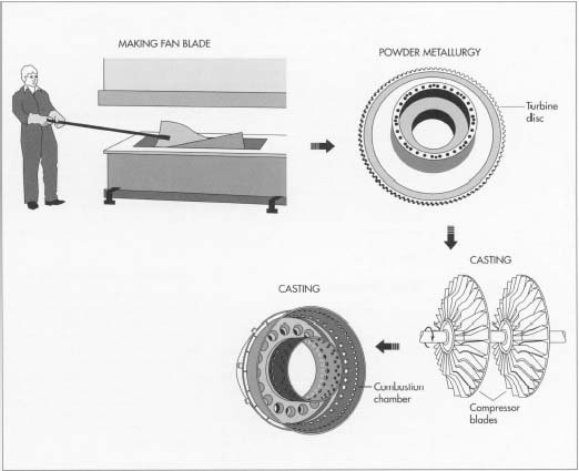
- 1 In jet engine manufacture, the various parts are made individually as part of subassemblies; the subassemblies then come together to form the whole engine. One such part is the fan blade, situated at the front of the engine. Each fan blade consists of two blade skins produced by shaping molten titanium in a hot press. When removed, each blade skin is welded to a mate, with a hollow cavity in the center. To increase the strength of the final product, this cavity is filled with a titanium honeycomb.
Compressor disc
-
2 The disc, the solid core to which the blades of the compressor are
attached, resembles a big, notched wheel. It must be extremely strong
and free of even minute imperfections, as these could easily develop
into fractures under the tremendous stress of engine operation. For a
long time, the most popular way to manufacture the disc entailed
machine-cutting a metal blank into a rough approximation of the desired
shape, then heating and stamping it to precise specifications (in
addition to rendering the metal malleable, heat also helps to fuse
hairline cracks). Today, however, a more sophisticated method of
producing discs is being used by more and more manufacturers. Called
powder metallurgy,
it consists of pouring molten metal onto a rapidly rotating turntable
that breaks the metal into millions of microscopic droplets that are
flung back up almost immediately
due to the table's spinning. As they leave the table, the droplets' temperature suddenly plummets (by roughly 2,120 degrees Fahrenheit—1,000 degrees Celsius—in half a second), causing them to solidify and form a fine-grained metal powder. The resulting powder is very pure because it solidifies too quickly to pick up contaminants.
 Turbine blades are made by forming wax copies of the blades and then immersing the copies in a ceramic slurry bath. After each copy is heated to harden the ceramic and melt the wax, molten metal is poured into the hollow left by the melted wax.
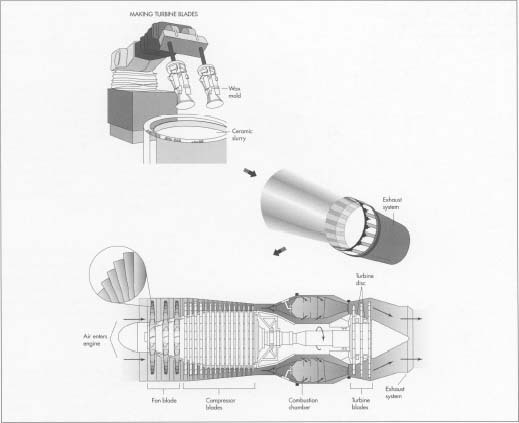
A jet engine works by sucking air into one end, compressing it, mixing it with fuel and burning it in the combustion chamber, and then expelling it with great force out the exhaust system. - 3 In the next step, the powder is packed into a forming case and put into a vacuum. Vibrated, the powder sifts down until it is tightly packed at the bottom of the case; the vacuum guarantees that no air pockets develop. The case is then sealed and heated under high pressure (about 25,000 pounds per square inch). This combination of heat and pressure fuses the metal particles into a disc. The disc is then shaped on a large cutting machine and bolted to the fan blades.
Compressor blades
- 4 Casting, an extremely old method, is still used to form the compressor blades. In this process, the alloy from which the blades will be formed is poured into a ceramic mold, heated in a furnace, and cooled. When the mold is broken off, the blades are machined to their final shape.
Combustion chamber
-
5 Combustion chambers must blend air and fuel in a small space and work
for prolonged periods in extreme heat. To accomplish this, titanium is
alloyed to increase its ductility—its ability to formed into
shapes. It is then heated before being poured into several discrete, and
very complex, segment molds. The sections are removed from their
molds, allowed to cool, and welded together before being mounted on the engine.
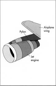 A jet engine is mounted to the airplane wing with a pylon. The pylon (and the wing) must be very strong, since an engine can weigh up to 10,000 pounds.
Turbine disc and blades
- 6 The turbine disc is formed by the same powder metallurgy process used to create the compressor disc. Turbine blades, however, are made by a somewhat different method than that used to form compressor blades, because they are subjected to even greater stress due to the intense heat of the combustor that lies just in front of them. First, copies of the blades are formed by pouring wax into metal molds. Once each wax shape has set, it is removed from the mold and immersed in a ceramic slurry bath, forming a ceramic coating about .25-inch (.63-centimeter) thick. Each cluster is then heated to harden the ceramic and melt the wax. Molten metal is now poured into the hollow left by the melted wax. The internal air cooling passages within each blade are also formed during this stage of production.
- 7 The metal grains in the blade are now aligned parallel to the blade by a process called directional solidifying. The grain direction is important because the turbine blades are subjected to so much stress; if the grains are aligned correctly, the blade is much less likely to fracture. The solidifying process takes place in computer-controlled ovens in which the blades are carefully heated according to precise specifications. The metal grains assume the correct configuration as they cool following their removal from the ovens.
- 8 The next and final stages in preparing turbine blades are machine-shaping and either laser drilling or spark erosion. First, the blade is honed to the final, desired shape through a machining process. Next, parallel lines of tiny holes are formed in each blade as a supplement to the interior cooling passageways. The holes are formed by either a small laser beam or by spark erosion, in which carefully controlled sparks are permitted to eat holes in the blade.
Exhaust system
- 9 The inner duct and the afterburners of the exhaust system are molded from titanium, while the outer duct and the nacelle (the engine casing) are formed from Kevlar. After these three components have been welded into a subassembly, the entire engine is ready to be put together.
Final assembly
- 10 Engines are constructed by manually combining the various subassemblies and accessories. An engine is typically built in a vertical position from the aft end forward, on a fixture that will allow the operator to manipulate the engine easily during build up. Assembly begins with bolting the high pressure turbine (that closest to the combustor) to the low-pressure turbine (that furthest from the cumbustor). Next, the combustion chamber is fastened to the turbines. One process that is used to build a balanced turbine assembly utilizes a CNC (Computer Numerically Controlled) robot capable of selecting, analyzing, and joining a turbine blade to its hub. This robot can determine the weight of a blade and place it appropriately for a balanced assembly.
- 11 Once the turbines and combustion chamber have been assembled, the high and low pressure compressors are attached. The fan and its frame comprise the forward most subassembly, and they are connected next. The main drive shaft connecting the low pressure turbine to the low pressure compressor and fan is then installed, thus completing the engine core.
- 12 After the final subassembly, the exhaust system, has been attached, the engine is ready to be shipped to the aircraft manufacturer, where the plumbing, wiring, accessories, and aerodynamic shell of the plane will be integrated.
Quality Control
As production begins on a newly designed engine, the first one built is designated a test engine, and numerous experiments are run to test its response to the various situations the engine model will encounter during its service life. These include extreme weather conditions, airborne debris (such as birds), lengthy flights, and repeated starts. The first engine built is always dedicated to quality testing; it will never fly commercially.
Throughout the entire process of building an engine, components and assemblies are inspected for dimensional accuracy, responsible workmanship, and material integrity. Dimensional inspections are undertaken in many different ways. One common method is CNC inspection. A coordinate measuring machine (CMM) will inspect key features of a part and compare them to the designed dimensions. Parts are also inspected for material flaws. One method is to apply a fluorescent liquid over the entire surface of a part. After the liquid has migrated into any cracks or marks, the excess is removed. Under an ultraviolet light any surface imperfections that could cause premature engine failure will illuminate.
All rotating assemblies must be precisely balanced to insure safe extended operation. Prior to final assembly, all rotating subassemblies are dynamically balanced. The balancing process is much like spin-balancing the tire on your car. The rotating subassemblies and the completed engine core are computer "spun" and adjusted to insure that they rotate concentrically.
Functional testing of a finished engine takes place in three stages: static tests, stationary operating tests, and flight tests. A static test checks the systems (such as electrical and cooling) without the engine running. Stationary operating tests are conducted with the engine mounted on a stand and running. Flight testing entails a comprehensive exam of all the systems, previously tested or not, in a variety of different conditions and environments. Each engine will continue to be monitored throughout its service life.
Where To Learn More
Books
Moxon, Julian. How Jet Engines Are Made. Threshold Books, 1985.
Ott, James. Jets: Airliners of the Golden Age. Pyramid Media Group, 1990.
Peace, P. Jet Engine Manual. State Mutual Book & Periodical Service, 1989.
Periodicals
Brown, David A. "Norwegians Expect to Develop Family of Radial Inflow Turbine Engines." Aviation Week & Space Technology. November 10, 1986, p. 63.
Kandebo, Stanley W. "Engine Makers, Customers to Discuss Powerplants for 130-seat Transports." Aviation Week & Space Technology. June 17, 1991, p. 162.
Kandebo, Stanley W. "NASA-Industry Propulsion Team Addressing HSCT Environmental Issues." Aviation Week & Space Technology. November 25, 1991, p. 58.
Proctor, Paul. "Advanced Fuel Systems Crucial to High-Speed Transport Progress." Aviation Week & Space Technology. February 9, 1987, p. 45.
"Going with the Flow in Jet Engines." Science News. July 30, 1988, p. 73.
— David Harris
I am a M.S. student in manufacturing engineering and for doing my final project which subject is optimization of a special machine tool for blade machining, I need some more information about turbine blades, the most important of them is: dimension range of turbine blades especially width of blades. I just want to know the max. and min. width of turbine blades which are used in either jet engines or power plants. I would be very thankful if you help me with this problem.
Thanks for the information which is very helpful in enhancing our knowledge level.
Further, I would like to know some information on the following. I hope it could be answered.
1)What is PRECISION FORGING?
2)Whether Compressor and Turbine blades AEROFOIL FEATURES are just forged and polished?
3)Whether, "prodcuing slightly (1-1.5 mm) thicker aerofoil on compressor/turbine blade forging and subsequently removing the extra thickness by High Speed Machining will have any adverse effect as far as functioning of the blade is concered? If so what is the effect.
I would be very thankful if the above questions are answered